Ray Karadayi
President & CEO of Applied Automation Technologies
30+ years of experience in developing software for metrology and machine interfaces
Applied Automation Technologies, Inc.
Established in July 1987
Specialized in metrology-based measurement and automation software
• CAD based CMM software since 1987
• CMM software for NC machine tools since 1992
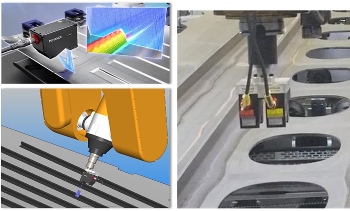
• Shop floor – factory wide metrology data collection
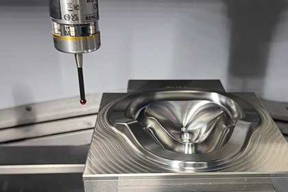
• How metrology data is created – traditional – on machine
• How to integrate metrology software for on machine measurement
• Verification and traceability
• Other factors that affect the machining process
• Calibration and tool correlation
• Contact, non-contact
• Relationship of Metrology data to Machine tool parameters
• Smart machining process automation – Measure – Cut – Measure
• Black box approach with machine geometry settings
• NCFIT reposting with actual part measurement data
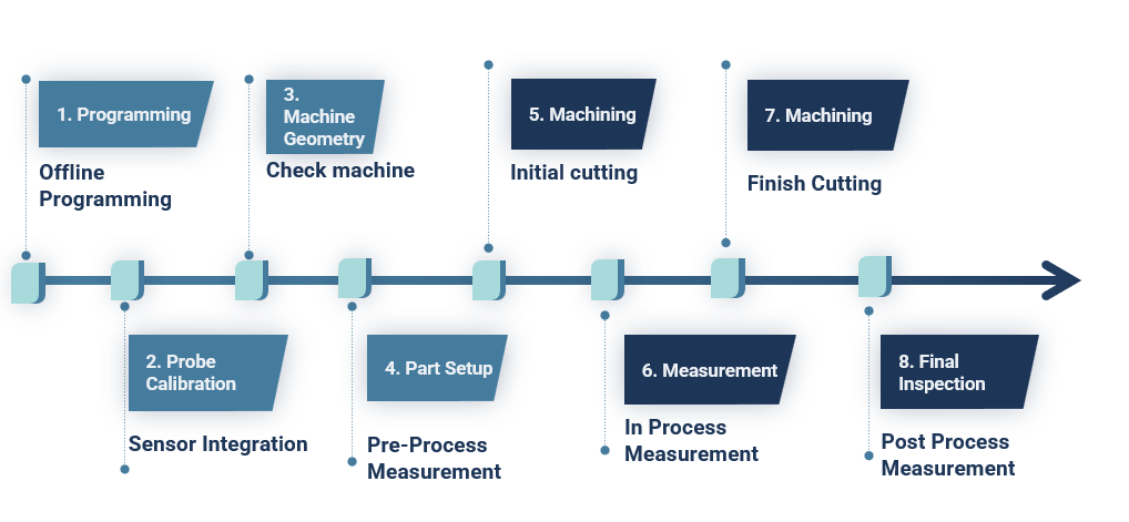
1. Programming
2. Probe Calibration
3. Machine Geometry
4. Part Setup
5. Machining
6. Measurement
7. Machining
8. Final Inspection
• Meet tolerance and dimensional requirements
• Achieve efficiency at minimum cost
• Digitalize metrology data within the machining center and factory
• Use metrology data to help machining
• Measure and create metrology at source
• Convert metrology data into meaningful manufacturing information
• Distribute this information as feedback to the machine and factory

• Science of dimensional measurement
• Calculate geometric features with high accuracy
• Use advanced filtering and fitting algorithms
• Adapt to specified datum definitions
• Calculate GD&T tolerancing values: Position, Size, Form, Profile
• Maintain traceability of known standards and artifacts
• Most reliable method for generating metrology information
• Not efficient for closed-loop metrology
• High precision parts may need to be moved between CMM and NC
• Labor intensive and expensive
• CMMs used for verification and traceability
• Expensive and part-specific
• Hard to revise and modify
• Requires calibration with master part
• Usually needs human operator
• Limited measurement capability
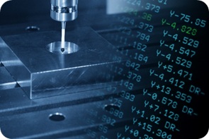
• Touch probes and dial gages are used to locate parts with manual human interface
• All calculations are done at G-Code level with simple mathematics
• Points are measured unidirectionally along machine axis
• Efficient Precision part manufacturing require high accuracy measurement methods
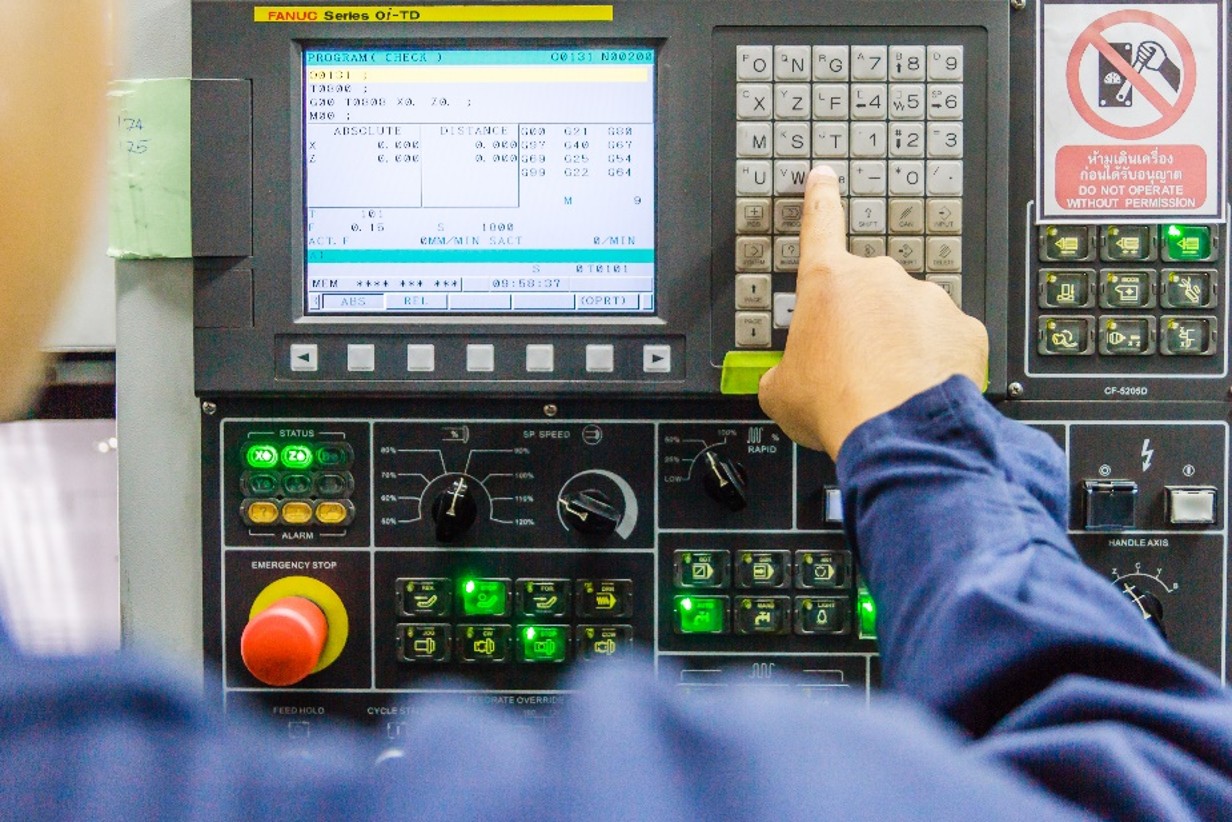
• Machine tool controller with direct interface cable
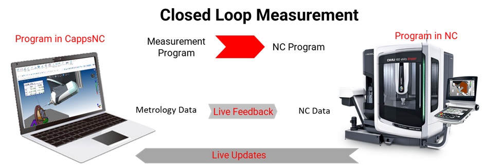
• CappsNC: CMM software for NC machine tools

• Measurement program and NC program with live updates
• Metrology software integral to machine tool via direct interface
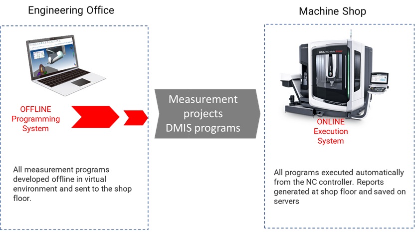
Offline Programming System
• Measurement programs developed offline from CAD
• Sent to shop floor for execution
• DMIS programs and engineering office integration
• Reports generated and saved automatically
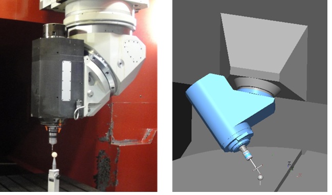
• Generate programs from CAD using virtual machine models
• Build and define probes and laser sensors graphically
• GD&T and report programming
• Automatic collision avoidance and 5-axis programming
• Coordinate system creation and work-offset feedback
• Generate Measure-cut-measure strategy
• Verify program and NC G-Code posting
• Verify geometry for trusted manufacturing
• Use master artifacts like tetra-gage or ball bar
• Measure linear and squareness errors
• Monitor head and table errors over time
• Measure and monitor geometrical errors
• Rotation axis directions and offsets
• Apply corrections
• Document data for SPC and predictive maintenance

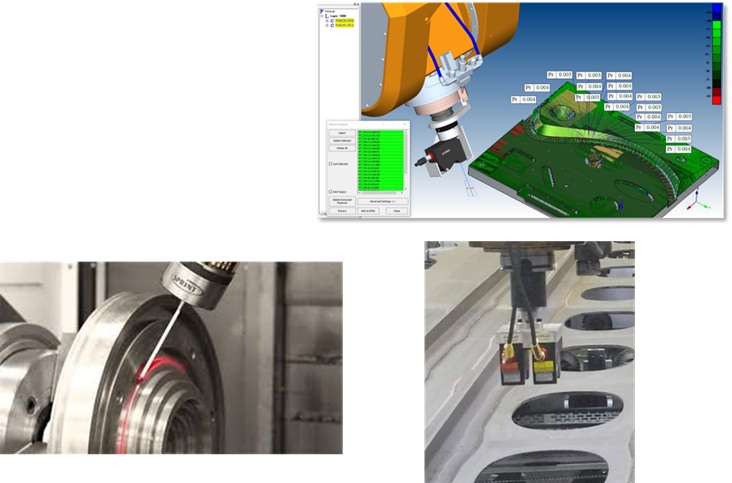
• Kinematic touch probes
• Strain gage multi-directional probes
• SPRINT analog scanning interface
• Non-contact laser interface
• CCD camera sensors
• Probe electronic length and radius
• Detect lobing errors
• Auto detect run-out offsets
• Calibrate multi-tip stylus configurations
• Head misalignment error calculation
• Verification reports
• Eliminate probe errors efficiently
• Latency, material, color, lighting calibration
• Sensor alignment and focal point offsets
• Multiple laser calibration
• Non-contact blue light laser scanners
• Primary goal: Produce parts with Dimensional Intergrity
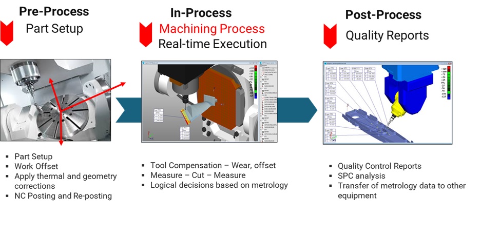
• Part setup and work offset
• Work Offset
• Apply thermal and geometry corrections
• NC Posting and Re-posting
• Tool compensation
• Measure → Cut → Measure
• Logical decisions based on metrology
• Quality Control Reports
• SPC analysis and data transfer
• Transfer of metrology data to other equipment and systems
• Create metrology info on machine
• CAD-based CMM software for advanced results
• Convert measurement data into machining parameters
• Automatic machining adjustments
• Dimensional specs met with complete reports
• Precise setup for 6DOF coordinate system
• Complex work offset from CAD and datum definitions
• Apply to machine kinematic constraints
• Transfer offsets from spindle to sub for mill-turn
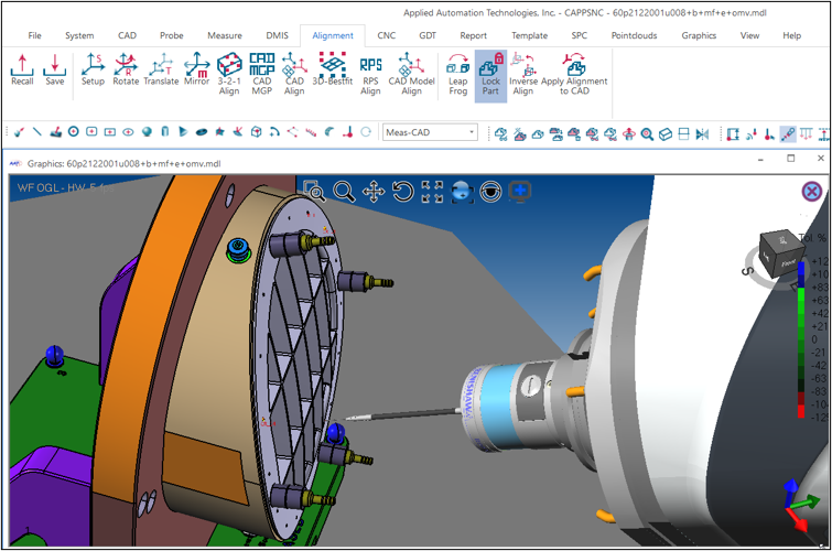
• Use multiple datum features
• Initial alignment with datum ball
• Measure fixture and part
• Calculate final work offset
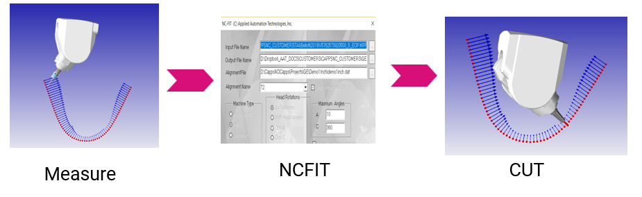
• Apply NCFIT for 5-axis head corrections
• Adapt NC program to part orientation and shape
• Adjust tool path and head orientation
• CUT → MEASURE → CUT → MEASURE
• Rough cut → Measure → Finish cut → Final report
• Dynamic tool compensation
• Set datum and work offset
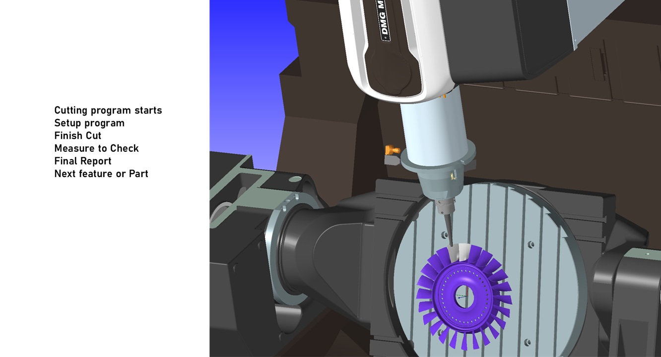
• Measurement program calls cutting programs
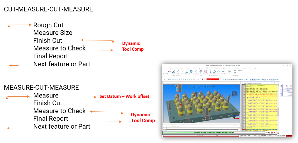
• Setup → Finish cut → Measure → Final report
• Feedback and work offset
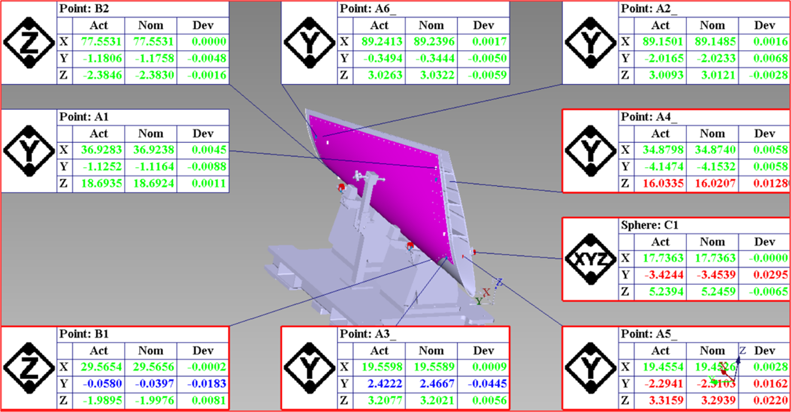
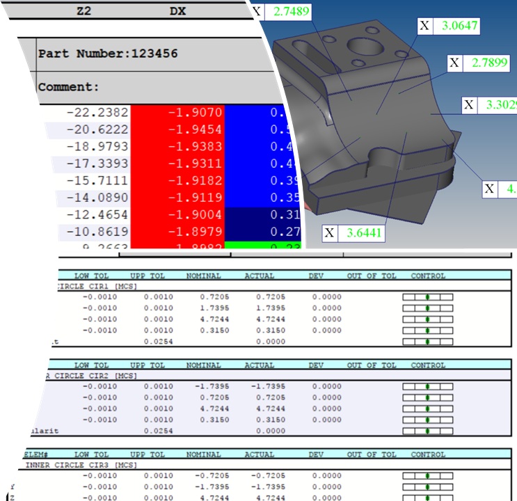
• CMM-style inspection results
• Full report capability on NC machine
• ISO & ANSI GD&T analysis
• Multiple datums and material conditions
• Form and profile analysis
• Graphical Go/No-Go reporting
• Real-time SPC data
• Auto email/text alerts
• Tool and part setup
• Data entry and alarm response
• Small errors cause downtime
• Closed-loop systems adapt automatically
• Improve OEE by reducing human dependency
• Measure and store all manufacturing data
• Metrology data reflects all manufacturing factors
• Convert data into manufacturing parameters
• Real-time feedback and predictive adjustments
• Single program controls all operations
• Robot installs part to main spindle
• Setup → Finish cut → Measure → Final report
• Move part to sub-spindle
• Setup check → Finish cut → Measure → Final report
• Robot loads next part
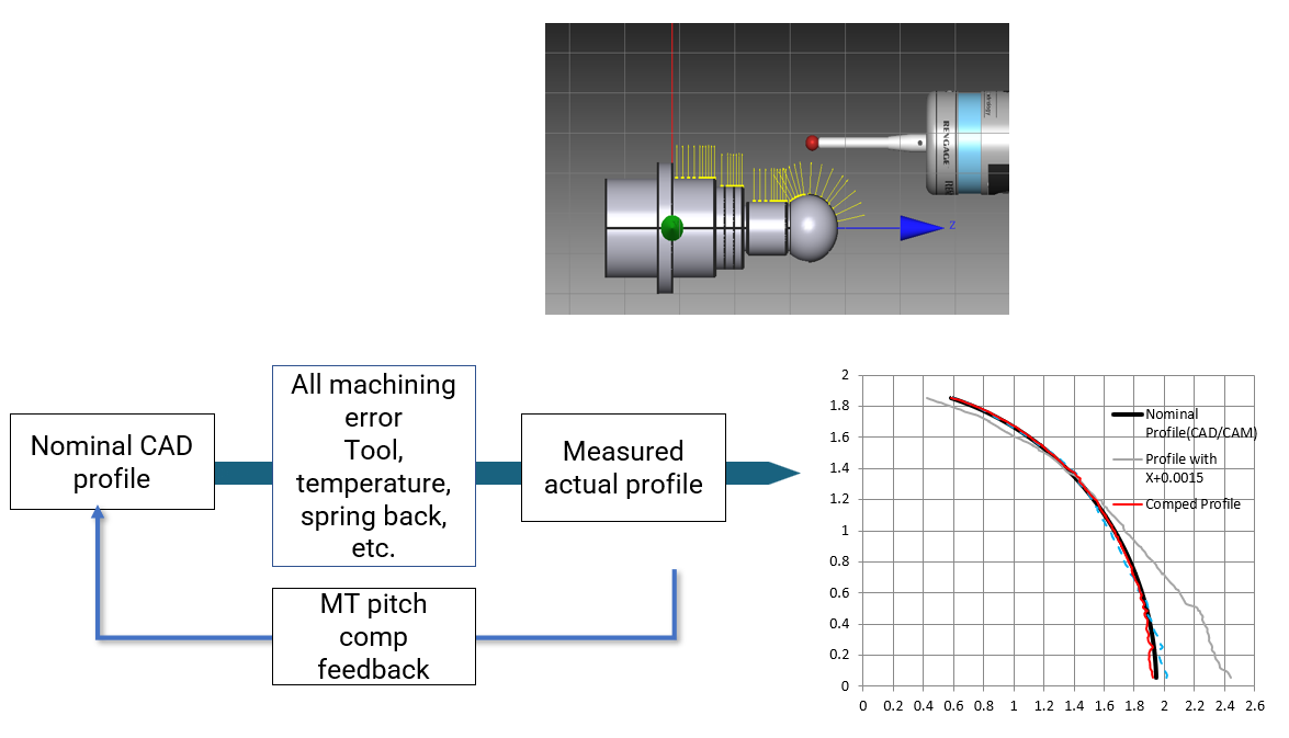
• Dynamic tool offset and datum setup
• Use machine error map for compensation
• Adjust for tool, temperature, spring back
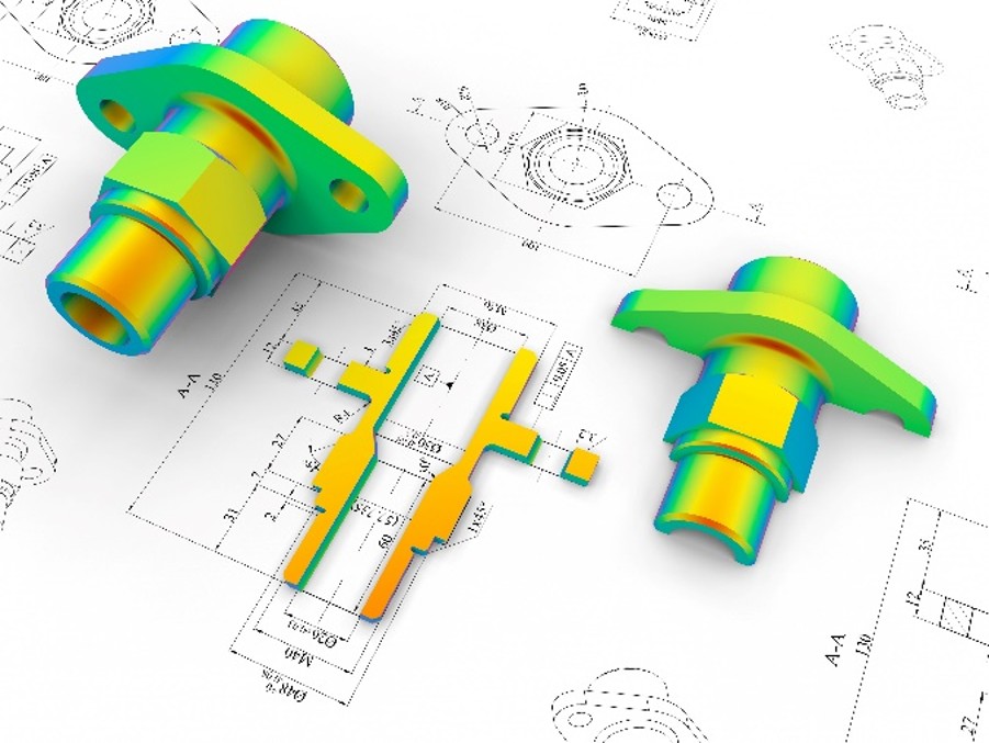
• Compare nominal CAD profile to measured profile
• Apply pitch compensation feedback
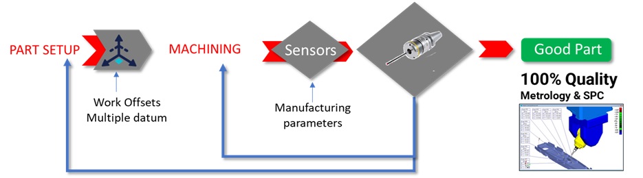
To produce parts that are dimensionally correct regardless of the changing parameters by using closed loop feedback at the minimum manufacturing costs
•Part Setup – 6DOF work offset
•Flexible datum multiple datum structure
•NCFIT– Adapt G Code to Part Shape
•Closed loop dynamic tool compensation
•Control manufacturing parameters
•Achieve perfect finish
•Provide complete measurement reports
•Create data for historical monitoring
•Reduce dependency in external measurement
•Remove human factor from manufacturing
•Enable Smart Machining with Closed loop feedback
•Achieve Industry 4.0 – Digital Manufacturing