Laser Scanning on Machine Tools Delivers Fast, Accurate Measurement in Adaptive Manufacturing Workflows
Dimensional measurement on the machine tools has been used in industry for several decades, as the need to gather faster and more accurate data grows, new probes and non-contact sensors are being developed and integrated within the machining center .
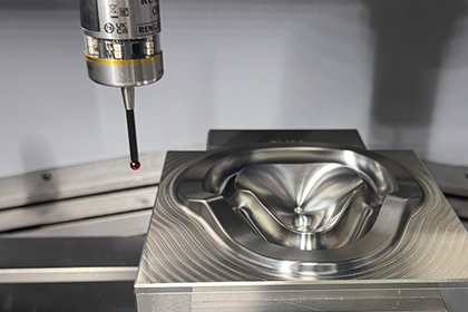
The recent surge, especially in aerospace manufacturing helped fuel the innovation in integration of laser sensors for on machine quick data collection. Figure 2 shows an example of Blue Light Laser Sensor Integration on a 5-axis machining center used for composite manufacturing.
Laser Sensor Integration and Its Point Cloud
A Keyence LJ-V7000 series laser line scanner can be integrated as a measurement sensor on a machine tool. These sensors are traditionally used to measure features that are moving in front of it while the sensor is stationary.
Keyence LJ-V7000 series blue light laser
At each trigger, the blue light sensor produces several points along a line in a coordinate system attached to the sensor frame. This coordinate system needs to be calibrated and data transformed to merge with the machine position.
Sensor coordinate system
The point data gathered from the sensor model used is along a line with up to 800 points at each interface with 50 micron apart.
Close up of a sensor data
The laser line scanner sensor focal point is the point in the middle of the sensor active region. The machine tool is commanded to bring this point to the intended position during a program execution. This is also the point where all the sensor calibration offsets are calculated.
Sensor focal point
The blue light sensor is attached to the spindle of the machine by a specially designed bracket. This allows the sensor to be kept within the tool magazine of the machine for automatic loading and unloading.
Blue light sensor attachment to the machine tool spindle
Shiny metal surfaces:
Calibration and tooling balls that are not coated with non-reflective material has been used to test the data quality. Since these types of artifacts are used both for calibration as well as datuming spheres, point cloud quality has been tested and results were good as in the image below.
Scan data on a shiny calibration ball
Both polished and rough composite materials can be measured with a blue light laser sensor. The quality of the data gathered on these parts is well-suited to production pieces.
Scan data on a polished carbon fiber composite
Plastic injection mold parts are also good candidates for laser scanning.
Scan data on a black plastic part
Metal machined parts especially for aerospace engine components such as airfoils are also can benefit from non-contact scanning with blue light laser.
Scan data on a metal part
The blue light laser sensor system integration with the machine must provide precise data latching between the machine position and the laser data. This is done by using a trigger signal from an external device and capturing the machine position and the laser data with time stamps. The two sets of data are merged into single coordinate system producing the point cloud of the surface scanned. This system allows a very fast and robust data capturing between the two separate systems and very easy to integrate to the machine tool controller as it uses existing I/O channels.
Blue light and machine tool controller data synchronization
Measurement Feedback for On Machine Tool Measurement
Blue Light Laser Sensor Integration with the Machine Tool: The laser sensor is used to create a point cloud by scanning a part and ultimately calculate metrology information about the part on the machine. Part of this information will be used to provide feedback to the machine tool controller so that the benefits of having an on-machine measurement can immediately be applied to on manufacturing process. In order to achieve this goal, the laser sensor will have to be introduced into the system in relation to other tools and calibrated to other tools such as a drill bit or a water jet focal point.
A nominal mathematical model of the sensor is defined and entered in the machine tool controller as one of the tools. Once the calibration is performed, the actual tool data will be uploaded to the controller or can be held by the software.
Blue light laser offsets and directions
Blue light Laser tool definition into controller
The relationship of the sensor coordinate frame to machine tool control coordinate system has to be calibrated. This is completedby scanning a calibration ball at different sections. The software then fits this data to calculate the laser frame coordinate system.
Calibration: A master ball reference sphere will be used for the calibration first measured by using a touch probe prior to the blue light laser sensor. The laser sensor attached by the spindle on the machine can be indexed to any orientation which the machine can move like a touch probe or the cutting tool. The head orientations that will be used in a program can be calibrated to achieve more accuracy. This is done by automatically generating programs based on the desired head positions and executing these programs automatically. A calibration program for all the head positions in a scanning program can also be created automatically to quickly calibrate these positions. Calibration process is an automatic and iterative process. Once a program is generated, this program is stored within the machine tool controller and can be run by the operator or as a part of a program sequence. Based on the calibration quality, software interacts with the controller and can iterate the process.
Generating a calibration program from a grid
Calibration offset reports
A standard test like ISO 10360-5 can be performed to verify its calibration and calculate an uncertainty value for the whole system. For this test of blue light laser sensor Integration, a program is generated to measure a tooling ball by using the calibrated head orientations.
Examples of tooling ball measurement at different head orientations
The measurement results are then compared to determine the largest deviation. This test can be completed in less than 10 minutes and generate an uncertainty statement before running the actual measurement programs. Individual feature calculations are reported to determine the uncertainty. Final sphere calculation that uses all the point clouds from each head orientation can also be performed to get an accuracy statement of all the point cloud data scanned by different head positions. The following is an example of a report from this calculation:
On-machine part measurement with blue light laser:
A scanning program can be created offline by using a CAD model to create point cloud representation of surfaces. In case of scanning a trim line of a part that will be manufactured, a scanning program can be created directly from the cutting program. By scanning the surfaces along these trim lines, the exact shape of the part profile is created and can be used for further analysis.
Point cloud generated along a trim line of a component and a detailed view of a section
Curve extractions:
After blue light laser scanning a part, curves can be created from the point cloud in several ways. A 2D spline curve can be extracted automatically by specifying the section coordinates for an airfoil blade or for a mold being manufactured on a machine. Figure 21 shows a point clouds of a blade and sectional curves extracted from it. These curves can then be used to create best fit alignments, profile reports, or calculate the airfoil parameters.Irregular curves extracted from an NC cutting program cutting path can also be dropped on to the point cloud to create the exact trimming line profile of a part. This data then can be used to correct the multi axis machine path to make sure the part is manufactured without requiring a long setup up process and avoid scraps. The Figure 22 shows a magnified error profile of a curve extracted from a point cloud of a composite aerospace component.
Curves extraction from point cloud of a blade
Profile error of a NC trimming path on a point cloud surface
Geometric feature extraction:
Measurement of geometric features are necessary for each pre-process need such as setting up a part coordinate frame before cutting and post-process to create a full dimensional inspection report of the part. Initial part setup could be by measuring a king and a queen pin on a composite part or datum spheres located around the part to create an alignment. These coordinate systems can then be used by the reposting process to adapt the cutting program to the part orientation or simply sent to the controller as a work offset. After the part is manufactured, a finished part can be scanned and its trim or edge profiles can be reported as a preprocess analysis. Any drilled holes can be extracted from the point cloud and their true positions can be reported along with any other GD&T call outs creating a final inspection report. Since unlike a manual or offline operation where an operator can interact with the software to perform these calculations, for the NC machine, these feature extractions are done automatically without any user interaction. The image below shows point clouds and extracted features from a NAS (National Aerospace Standard) part. In this example, first the three tooling balls are scanned, and spheres are extracted. An alignment is created from these spheres to match the CAD model. The calculated alignment is uploaded to the controller as a work offset and the rest of the part is scanned. Ultimately, the all the geometrical features are extracted, and their dimensional reports are created.
Blue light measurement of a standard NAS part
Detailed profile report of an extracted circle
Position report of a circle extracted from the point cloud
Adaptive Manufacturing with point cloud data In order to achieve a self-adapting manufacturing process, dimensional measurement programs can be utilized at several different stages of the manufacturing cycle. During pre-processing, part location and orientation can be measured and used as a work offset to help part cutting, Part surface profile can be measured before the final finishing process to calculate tool wear and offset correction parameters for specific surfaces. As post-process final inspection, a CMM like complete measurement program can be executed to generate a final metrology analysis of the finished product for final inspection reports and statistical trend analysis. Manufacturing of large and non-rigid parts like most of the aerospace components presents challenges in many ways. Composite parts could be hard to fixture to produce a smooth cutting process. In addition to their large and usually non-rigid structures, these parts could also be deformed coming from the heat treatment process or distorted by the holding fixtures. Especially trimming a composite part with a water jet machine requires the profiles along the trimming lines to be within certain tolerance in order to have a smooth finish and even avoid a crash. By using a blue light laser scanner, a process can be put in place to not only setup up and prepare the part easily for the cutting process but actually automate it so that it could be performed with minimum interaction with the operator.
1) Scan datum balls to create a coordinate system. Tooling balls used for the part alignment are scanned and their spheres are extracted from the point cloud. These are used to create an alignment according to part setup requirement.
Tooling ball scanning and geometry extraction from point cloud
Scan trimming and drilling paths as defined from the cutting program: Figure 22 shows an example of the magnified profile error over a cutting tool path.
Apply re-posting to fit the cutting programs to part location and shape: The original cutting programs are processed through a reposting process and a new cutting program is generated. Once reposting is done, the regenerated cutting tool program be simulated for verification before running on the machine.
Perform the trim and drill operation: The new adapted cutting program can now be executed to produce the part.
Post-process inspection: A final scanning program is run on the finished part to generate a complete part measurement report.
Simulation of a reposted program with the actual part orientation and shape
NC Program Reposting: NC program reposting is the process of regenerating an NC cutting program based on the measured part orientation and part shape. This process takes a nominal cutting program as an input and applies the actual part information from the measurement results such as the point clouds generated by scanning a part. Figure 27 shows the process of reposting a cutting program.
Reposting of a NC program code by using blue light laser data
A cutting program reposting helps with two problems during the manufacturing process.
A cutting tool location, usually the bottom of a cutting tool can easily be handled by applying a work offset within the controller for both part location and part rotation. However, when the tool orientation must match the actual part rotation, its G-Code program must be reposted to update the tool orientation as well. A grinding tool where the contact surface has to be at a precise orientation with the part or a water jet where the cutting vector must be precisely aligned are examples of this. Although some machine tool controllers can automatically adjust this orientation by using the work offset, in most cases this feature is not present or very difficult to use. NC program reposting for a 5 axis machine with a program using the A, B, C angles of the head or I, J, K vectors of the tool can recalculate these parameters maintaining the tool orientation with the part. Figure 29 shows a cutting path and head adapted to an actual part orientation.
Adapting tool vector and cutting path to measured part orientation
Sheet metal and composite parts that needs to be trimmed may be out of its actual shape due to fixturing of its non-rigid structure or the heat treatment process. Part’s residual stresses also changes its profile after a portion is removed. Especially trimming of these parts with a water jet cutting takes a long time to prepare or causes part defects. By measuring the part profile and reposting the cutting program to the actual part shape provides a very quick and inexpensive method which can also be automated. Figure 30 shows how an intended straight cut is made to fit the actual part shape through this process.
Adapting machine motion to actual part shape
In some applications, reverse engineering of the actual part shape is necessary to create a custom cutting program. This same process creates a digital twin. A part that needs to be reworked such as a repaired blade that needs to be finished on a 5-axis machine might require a custom cutting program. In this case, the measurement data such as the point clouds or extracted curves and geometrical features can be exported to a CAM system which can then create a custom cutting program for the parts exact location and shape.
For parts that had been repaired by welding material or parts being manufactured on an additive/subtractive machines, the actual welded or generated sections can be digitized and the actual curves exported to a CAM system which can create a custom fitting cutting tool path for the parts exact shape. Figure 31 shows an example of an airfoil repaired by welding and finished by a process like this.
An Airfoil finished after reverse engineering
Conclusions:
Laser Line Sensor Integration can be installed on a machining center by directly loading it like a cutting tool. This integration is very quick and very low cost and it can be adapted to multi axis machining centers. Having a point cloud metrology capability with a measurement software on an NC machine tool especially for large and non-rigid parts has great benefits.
Reduce setup time and cost:By integrating a closed loop measurement system with a blue light laser on the machine, the setup up and preparation time is drastically reduced.
Reduce setup costs: Dedicated expensive holding fixtures are not necessary as the part setting and program fitting is done by using the measurement data.
Reduce dependency on external equipment: Having an on machine measurement capability both with the touch probe a blue light laser eliminates the need to bring external measurement equipment to the machine volume such as the laser trackers or portable arms or eliminates the need to move the part to an external measuring machine.
Cutting program fitting: Using the point cloud data generated directly on the machine, cutting program can be reposted and adapted to the actual part location and shapes.
Automated closed loop manufacturing: As the blue light sensor can be held within the machine tool magazine, measurement and cutting process can be automated except for manually connecting a data interface cable
Reduction on additional repair and scrap:Parts are manufactured adaptively by using the readily available metrology data which ends up reducing the scraps generated or the need to repair parts.
Increase product quality: By measuring a part on the machine without having to remove it and adjusting machining parameters based on the measurement results allows to manufacture high precision parts. Knowing the part dimensional quality and metrological characteristics before removing it from the machine has great benefits and improves the overall performance of a manufacturing facility.
Manufacturing system factory control: Adaptive measuring systems work with the machining center as a peer to peer secured interface, but they are also on the network for measurement data collection and reporting. Measurement results from machines used in a manufacturing facility can be collected in a database and used to monitor the overall factory performance. Evaluating and comparing this kind of data allows better decision making and help plan for future manufacturing strategies.
Ray Karadayi Applied Automation Technologies, Inc. 1688 Star Batt, Rochester Hills, MI, 48309 USA Phone: 248-340-6934 ray.k@aat3d.com
Subscribe to our newsletter
Thank you! Your submission has been received!
Oops! Something went wrong while submitting the form.