CAPPS 2026 Release represent that most comprehensive release to date. The release focuses on productivity and functionality with large updates to NC-Fit and NC-Laser modules and is NIST certified.
Updated: 01.16.2026
Quality of Life
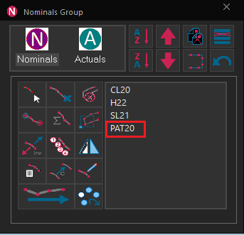
Added support for nominal pattern creation, which can be created from multiple feature types, cylinder, slot circles, contained in the pattern.
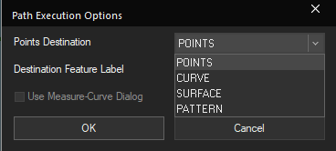
The Path Execution Options dialog allows a set of points to be saved as a Pattern.
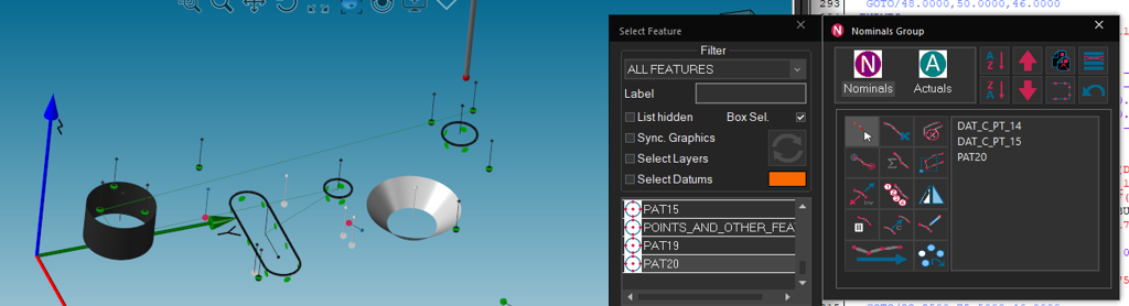
The Nominals Group (Path Options) dialog supports executing paths that include Patterns. Each element feature of the Pattern will be measured.
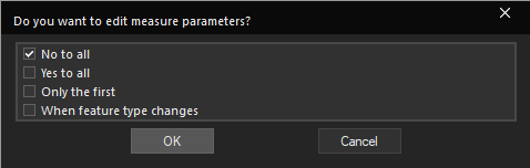
Executing a path from the Nominals Group (Path Options) dialog provides “every feature”, “only the first feature”, and “when the feature type changes” as additional choices for editing measure parameters.
“Add Elements to Path” has been added to the double-click context menu of Nominal Patterns in the TreeView.
The Nominal DMIS command for Pattern and Curve can be edited from the Program window.
The DMIS command for Nominals may be edited using the dialog, opened from the right-click menu, from the tree, or the text of the DMIS program itself.
The active alignment can be changed within the Output Feature dialogs.
Integrated the Advanced Surface Point operations into analog scanning
During execution, the Program window will scroll to keep the active command line in the middle of the window.
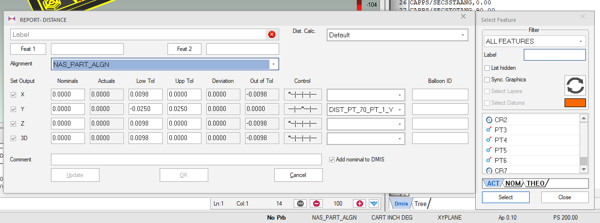
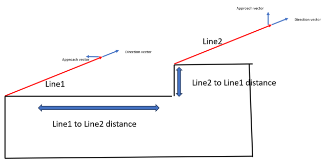
Added a function to evaluate distance calculation between two line-reducible features when their orientation is nearly perpendicular or parallel.
The first position point is allowed without collision avoidance during simulation. This is due to the common occurrence of a CAD model being loaded at the machine home and the probe being inside the volume when fits creating a program
The model of machine defined will be shown when starting CAPPS before a program is opened, with a VMM configured.
NIST software certified with feature fitting algorithms.
PTB software certified.
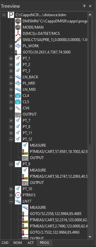
Prog Tree
The DMIS Tree tab has moved to the Tree View and is named PROG.
The new PROG Tree View tab now highlights and expands nodes during execution, like the obsolete DMIS Tree.
The features of a Nominal Pattern can be added to the path by double-clicking it in the Tree View and choosing Add to Path.
The features composing a Nominal Pattern can be edited in a dialog opened from DMIS or the Tree View.
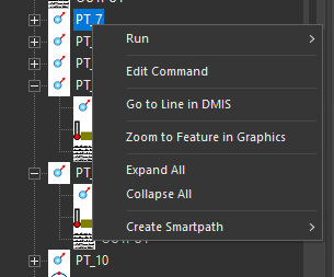
Added support for the function, Learn to Insert After, in the PROG Tree View.
When an OUTPUT follows a measure block, it will be indented in the PROG Tree View.
“Add to Path” command for a Nominal Pattern adds the pattern to the Path Options dialog, in place of its elements.
OUTPUT is used to identify writing to the report in the PROG Tree View.
Measurement
The measure points of Rectangular Slots can be shifted when teaching. (maybe UI that shows)
The Measure Curve dialog supports portable arm analog scanning.
Nominal Patterns and Curves can be created using the Construct dialog.
CAPPS-DMIS: This is not available for Geometric+ licenses.
Known curve scanning projects scan actuals onto the nominal curve for probe diameter compensation, vectors, and profile.
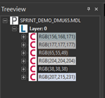
Clicking on a Layer or Color in the CAD Tree View will select all contained surfaces.
Teach from CAD for Corner Points is supported.
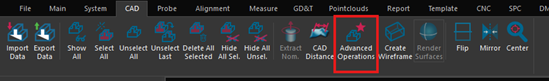
The Advanced CAD Operations dialog
new screen to increase or decrease the size of the CAD model.
Increase the Scale of the model.
Improved the speed of reading CAD files by 10%.
An Advanced Operations button has been added to the CAD ribbon menu, which was previously a right click in the graphics window.
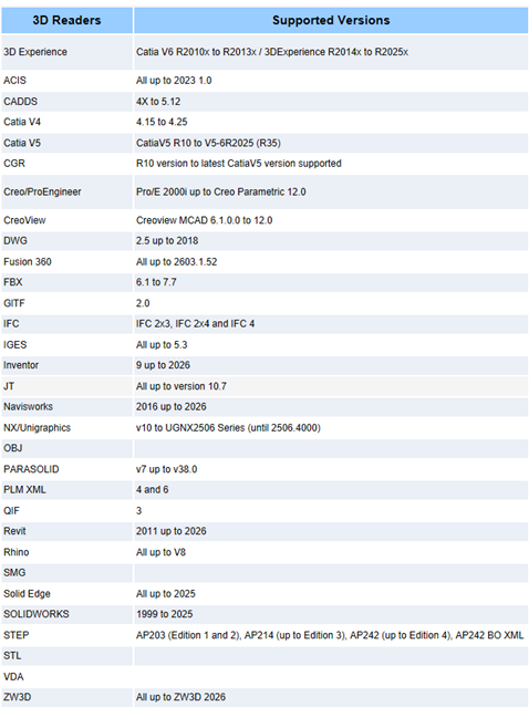
Updated support for the latest CAD versions.
Reporting
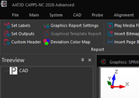
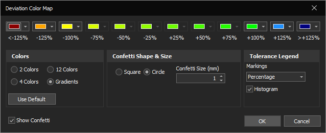
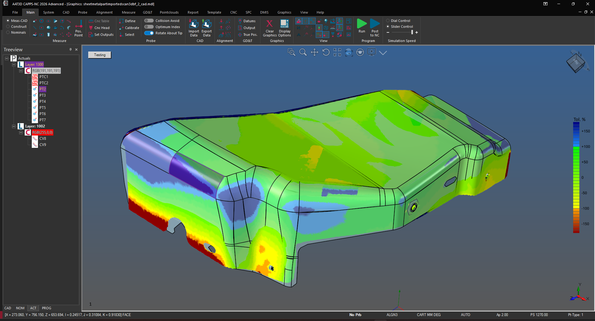
The Confetti Settings dialog has been renamed to Deviation Color Map.
dialog has replaced the Graphical Template Report’s screen for Confetti Settings.
Allows changing the tolerance legend between gradient and solid colors.
Improved the layout of the Deviation Color Map dialog and added the new option for the Tolerance Legend’s markings.
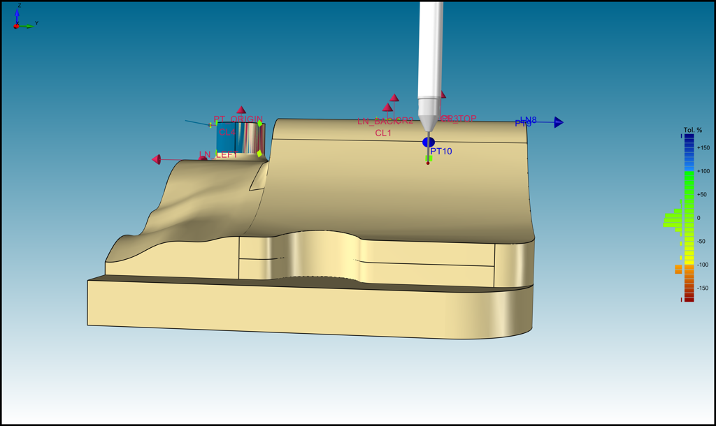
There is a new tolerance legend that applies a gradient to the colors selected.
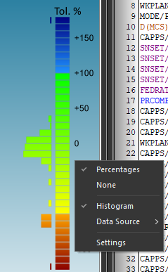
This includes a right-click context menu for changing the marking text.
The Deviation Color Map dialog can also be opened from this menu.
The Deviation Color Map dialog has a checkbox to control whether the histogram is shown.
A histogram can be shown next to the Tolerance Legend, based on each report line item’s Out of Tolerance value. This is available from the Legend’s right-click context menu.
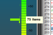
Clicking on a Histogram bar in the Tolerance Legend will show the number of report elements in that range.
Applying the out-of-tolerance color to the border and leader line of report templates can be disabled in the Display Properties screen of the Template Settings dialog.
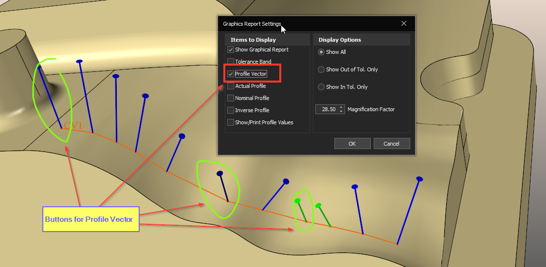
Converted profile vectors from arrows to lollipops.
Reporting Angularity with two datums is now supported.
Form can be included when reporting Perpendicularity, Parallelism, and Angularity.
The viewport number is no longer included when capturing images from the Graphics window.
Folders are no longer automatically created when executing commands such as SAVE\GRAPHICS,APPEND.
When reporting the distance between two lines, the second line will automatically be projected onto the plane formed by the first line’s approach vector. The auto-scroll behavior of the Grid report will scroll so that the bottom of the last report item is at the bottom of the window.
Added a setting to Draw Confetti at the Actual instead of nominals in the System Configuration dialog.
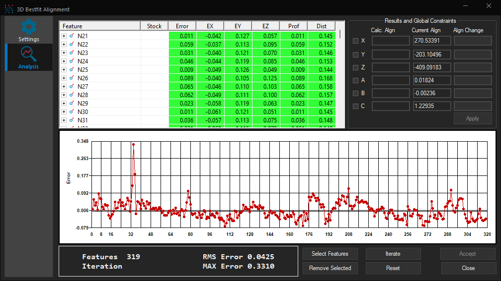
3D Best-Fit
The dialog was crowded. So, it was split into two pages: One for settings and one for 3DBF analysis.
Filtering. Example: A DMIS program has a 3DBF alignment in its program that uses PT1, PT2, …, PT100. When the program runs on the machine, there could be a chip in the part, or something similar, that leads to big errors in PT2, PT5, and PT20. Using these 3 points could lead to large errors in the calculated 3DBF alignment. Filtering is a new tool that was added to 3DBF algorithms to avoid using such problematic features. The settings page include Filtering section that allows the user to choose one of the following:
None. This means no filtering is used
Tolerance zone. In this case, the user enters lower and upper tolerances. Default is -/+ 0.1 mm in mm and -/+0.01 in inch. This is good if the user knows min and max part errors.
Sigma zone. In this case, upper and lower limits are numbers of standard deviation of feature errors. Default is -/+ 3 sigma. This is more dynamic and depend on the errors distribution unlike the Tolerance zone. Usually, it is used to filter out outliers.
How filtering works
Compare-to-Nominals; 3DBF alignment is calculated by fitting actuals to nominals. Errors from the features are calculated and features with errors outside the allowed Tolerance/Sigma range are removed; then the 3DBF alignment is recalculated.
Compare-to-Nominals: In the first iteration, and before calculating the 3DBF, features with errors outside the allowed tolerance are removed. The removed features won’t be used in the next iteration. If the user expects more features to get large errors during iterations, they can check “Apply filter during 3D Bestfit Iterations”. If none-filtered feature is out of the range, it will be removed in addition to the already removed ones.
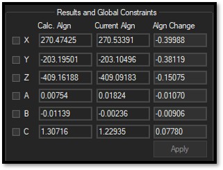
Analysis page. The calculated 3DBF alignment is displayed along with the current one, and the difference between them.
Calc. Algn = Calculated 3DBF alignment
Current Algn = Current alignment
Algn Change = “Difference” between current and calculated alignments.
User may change the values in Algn Change, then click Apply to see the effect of their change on the errors. There is no automation associated with the Apply button. It’s just to do “manual” analysis.
Features selected for 3DBF used to be cleared after clicking Accept. They are now left in the dialog to do further analysis.
CAPPS-DMIS
Improved the layout of the DMIS tab of the Measure Options dialog.
A default laser sensor for portable arms can be shown in the Graphics window.
Scanned curves can be compared to the nominal curve to calculate normals and profiles, when Compare to CAD is disabled.
Improved behavior of Measure Curve scanning for portable arms.
Removed the need for an extra button press to begin a scan.
Removed the button arm command to toggle single/continuous.
Point Density added to the Measure Options dialog.
Continuous points support for PMT Alpha arms.
When using a portable arm interface without a probe model defined, a handle and body will be drawn in addition to the stylus.
Disabled the Position Point button when using the Measure Curve dialog for portable arms.
Improved the tooltip for Point Density in Continuous Mode on the Measure Options dialog.
The Measure Point dialog will colorize the Continuous PT/Single PT button when online with a portable arm interface.
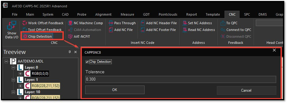
CAPPS-NC
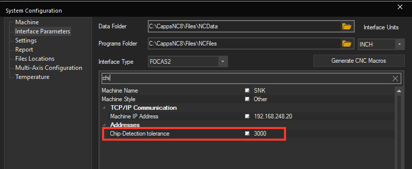
Chip detection is now supported. DMIS code write on and off is supported. Can be defined in CAPPS-NC .ini file. An error will be triggered if a measure point is off by this amount.
VMM files support multiple head configurations.
When reading work offset the U, V, and W axes are also displayed in the Data IO dialog.
Added 9 machine address system variables.
Enhanced the Probe Builder to support heads with rotating spindles.
The Machine page of the System Configuration dialog has settings to establish a connection to AATLC for real-time laser data.
Multi-head VMM now remembers the active head and applies a different Machine Home Position for each head.
The Data I/O window shows scan data detail when connected to receive real-time data from AATLC Server.
The Data I/O window reports total G-Code execution time.
If the Data I/O window is open when the Machine screen of the System Configuration dialog is opened:
A button to close the Data I/O window is available.
The connection settings for AATRMINC and AATLC are disabled.
CNCHEAD is a new DMIS command to initiate a head change.
Machine INI cncChangeHead is used for this macro.
G-CODE is generated to call the macro.
Improved the layout of the Work Offsets dialog.
The Work Offsets dialog has improved alignment selection.
Added a macro extern statement for Change Head to Siemens.
The inspection program’s name is shown in the Data IO window in place of the ???
For easy access by Execution stations when no program is open, the Data IO button has been added to the File ribbon menu.
VMM files support machines with an offset between the Spindle-Axis and C-Axis. The CAXIS2SPINDLEAXISOFFSET keyword allows this.
The Interface Parameters screen of the System Configuration dialog has a line to enter the new Change Head macro.
The Recall Alignment dialog will only provide the Work Offset Details tab when it was read from the machine. Ability to read workoffsets from the machine and display them in CAPPS-NC. It is possible to create simple work offsets offline
Added a Dwell Time setting for Heidenhain controllers.
Renamed the HSSB Dwell setting to Dwell Time for Makino and Fanuc controllers.
NC-Fit
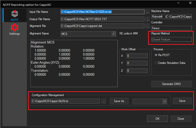
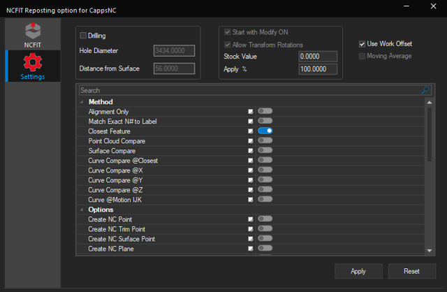
New layout of NC-FI, navigation uses a tree instead of icons and a separate settings tab.
NC-FIT will create intermediate labels for long moves when “Closest Feature” is selected.
Create all NC-FIT analysis files in a subfolder to keep the program folder clean with just the reposted program.
NC-FIT setting to create all repost data and output the NC program in a separate folder by incrementing.
Settings files can be saved and loaded.
Improvements in handling head angles, alarms, nominal data generation, and reporting to CSV.
NC-FIT will update the file name when reposting is configured to create files in separate folders so they can be opened after reposting.
The Output File Name selection dialog has been upgraded to select a folder without a file.
A default Output File Name will be used when one is not provided.
Messages will be shown if a problem is found with either the Input File Name or the Output File Name.
NC-FIT creates nominal points to match labels expected in the “Match Label” method. This is applied to the G-code
Configurations can be saved to new INI files.
Settings tab can be disabled, depending on the security setting.
Added a pop-up notification when changes are successfully saved or applied in the NC-FIT dialog.
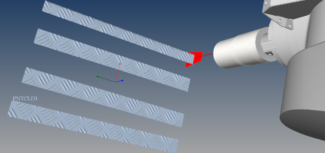
NC-Laser
Significantly improved graphics in terms or visibility of point clouds, scan lines, and rendered point cloud meshes.
Improved the accuracy of simulated laser scan data for programming using CAD.
Added a new DMIS command to control using CAD in laser simulation: CAPPS/LSRSIM,USECAD (or DEFAULT).
Thermal compensation is supported for laser-scanned point clouds.
Programs written for one brand of laser sensor are independent and can be used for another brand.
Laser simulation can work on machines that have 3 rotary axes on the head: A/B/C/S.
The Nikon and LK laser interface:
o Now supports calibration using real-time data.
Added support for real-time data from Nikon and LK lasers.
Has improved the speed of processing scan data.
Has improved device connectivity and detection. Automatically connect to Nikon and LK sensor when it is powered up or plugged in.
Integrated the Advanced Surface Point operations into the Laser scanning
Real-time laser data can be saved to a new .LASPTS file type to allow running the program offline.
AATLC: Keyence and Micro Epsilon improvements
Decreased the default tie delay for scan line processing to 1.
Status box auto-scrolling.
Hardware Support
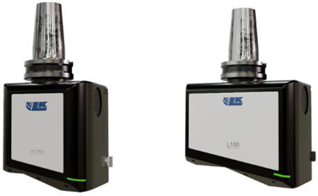
LK Scanner support for LC150x and L100 models
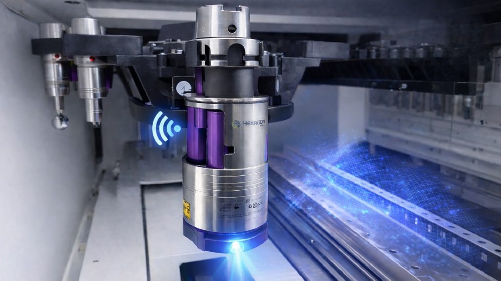
Internal development for the new Hexagon Laser interface for m&h LS-R-4.8.
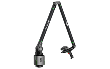
Added support for the PMT portable arm
Added support for TNC7 Heidenhain controllers.
Minor
The default gradient colors will be used for new installations of CAPPS.
Improvements to calculating nominals and profiles for scanned curves by using nominal curves.
Disabled best fitting as the default in the Form and Profile dialog; it must be selected.
Nominal sensor calibration is used when starting a new program.
Support for path execution in Auto mode for curves, surfaces, and point clouds.
The probe assembly and components will be visible by default for new installations and when the graphics settings file is missing.
The Highlight options in the Edge Settings dialog are saved when pressing OK.
Improved the performance of simulated point clouds in graphics.
o Press Red: deletes the last point.
o Hold Red: computes the feature.
• "Decimal Places For Points in DMIS" and "Decimal Places For Vectors in DMIS" have been added to the Settings screen of the System Configuration dialog under Math Parameters.
The list of features will be updated while executing a Nominals Group path. This allows a path canceled from the Measure dialog prompt to be resumed.
When using “Run From” to execute a program from a comment line and the first following command is a sensor activation, do not activate the previous sensor.
The Shading command has replaced Render Surfaces in the Main ribbon menu.
Templates will automatically be made visible when creating a template from a Feature’s context menu in the Graphics window.
Executing a portion of the program that begins with recalling a sensor no longer recalls the previous sensor.
Improved the layout of the Alignment Setup, Align M.G.P., Rotate Datum, Translate Datum, and Define Datum dialogs.
The list above includes all the significant changes since the CAPPS 2025 R2 release, announced in August 2025. More exciting features and enhancements are planned for the next major release of CAPPS, customer are welcome to reach out directly to discuss ideas and future needs!
Contact AAT for a download link and upgrade to your existing software. Contact us here
Subscribe to our newsletter
Thank you! Your submission has been received!
Oops! Something went wrong while submitting the form.