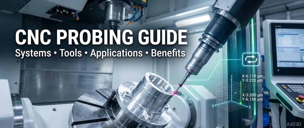
In precision manufacturing, tolerances are measured in fractions of a human hair. Traditional post-process inspection (moving finished parts to a separate inspection lab) is too slow and risks costly scrap. To prevent failure, modern shops integrate on-machine metrology directly into the machining cycle.
So, how does CNC probing work on an active shop floor?
At its core, CNC probing uses a physical-contact stylus or a non-contact laser to rapidly detect part features, capture surface topology, and digitize geometry. When sensors touch or scan a surface, they instantly transmit precise spatial coordinates back to the machine control.
Integrated with closed-loop software like CAPPS-NC, this process transforms metrology from passive observation into real-time feedback. Instead of stopping production to check accuracy, the CNC machine can adapt offsets and apply corrections during the cycle to improve process control and reduce scrap risk.
To define the technology clearly, it helps to draw a clear line between the machine shop and the quality lab. CNC probing uses an on-machine touch or non-contact sensor that measures a workpiece, a cutting tool, or a specific geometric feature and reports those spatial coordinates back to the machine's controller. The key distinction from traditional Coordinate Measuring Machine (CMM) inspection: on-machine probing measures the part while it remains clamped in its native fixture, whereas CMM inspection requires removing the part and isolating it.
The physics behind CNC Machine Tool Probing relies on signal transmission and a specific set of probe architectures. When a stylus makes physical contact with a machined surface, the micro-deflection sends a signal, via optical infrared beams or encrypted radio waves, to a receiver wired into the machine's electrical cabinet. This signal triggers a specialized controller command, most commonly the G31 skip command on Fanuc-based architecture. Axis motion stops within a fraction of a millisecond, capturing the machine position in its macro variable registry.
The hardware ranges from traditional kinematic-switch designs (where mechanical contacts break apart to open a circuit) to strain-gauge mechanisms that read micro-resistance changes, which reduce directional lobing errors. The controller uses this data to establish a work offset (translating the part's physical position into the machine's coordinate system) or a tool offset (compensating for tool wear or thermal growth).
Probing and inspection are not absolute synonyms. Probing equips the machine to navigate and cut accurately; pure inspection certifies the final geometry against the master engineering print.
No machine achieves perfect accuracy; there are only acceptable margins of error. Understanding on-machine measurement means understanding where precision is lost. The first factor is stylus calibration drift. As styli endure thousands of cycles, take minor impacts, or accumulate microscopic debris, the effective ball diameter registered by the controller begins to diverge from reality.
The second, and often more significant, factor is machine thermal growth. As spindles run shift after shift and ballscrews travel long linear distances, the machine's structure expands and shifts slightly. A probe mounted on a thermally distorted spindle will measure that distortion along with the part. Heavy roughing vibrations can also induce false triggers in sensitive mechanical probe bodies, creating unreliable data points.
Above all, the probe inherits the volumetric and positioning errors of the machine tool it rides on. If an X-axis ballscrew has a 10-micron pitch error, probing results will reflect that deviation. This is why routine recalibration against a traceable reference artifact, such as a Grade 5 tungsten carbide calibration sphere or a master ring gauge, matters.
It's also worth stating plainly: on-machine probing is not a substitute for a temperature-controlled CMM when certifying the tightest tolerance bands. Even a well-maintained machine tool typically can't match the isolated kinematics and thermal stability of a dedicated CMM for validating something like a ±3-micron aerospace profile. Probing helps prevent machining scrap; the CMM confirms the final result.
For new operators, the clearest way to explain how CNC probing works is to walk through the four-step touch-and-signal sequence.
The raw coordinate isn't useful on its own until the controller converts it into an action: shifting a G54 work offset, flagging an out-of-tolerance bore, or applying a tool-wear compensation. As shops move beyond the limits of basic macro programming, many are adopting closed-loop, software-driven metrology workflows (measure → adjust → cut → re-measure).
Solutions like NC-FIT closed-loop tool-path correction extend the process beyond simple datum shifts. (See our CNC Inspection & Probing Video Demos to see this in practice.) In practice, basic controller-native probing cycles work well for single, isolated measurements, but when a multi-axis program needs to adapt complex 3D toolpaths to the actual shape of a warped casting without pausing the process for manual correction, closed-loop metrology software is generally the better option.
In high-stakes manufacturing, claiming precision is easy; proving it takes discipline. Buyers evaluating a probing infrastructure should look for specific, documented deliverables: calibration against a traceable master artifact, paired with a clearly defined recalibration schedule. For Class III medical devices, calibration might be required at every shift change; for general aluminum production, it might instead be tied to tool-life intervals.
Experienced engineers also run correlation checks against CMM results to confirm that on-machine data tracks with lab data. As a concrete proof point, AAT3D’s capabilities are anchored by its NIST-certified geometric feature-fitting algorithms.
This certification covers the mathematics used to calculate lines, circles, cylinders, cones, and spheres from raw point-cloud data. It's worth keeping the claim properly scoped: NIST certification applies to the feature-fitting algorithms, not to the physical accuracy of every probe and machine combination on the floor. The certification confirms the software's calculations; the machine's mechanical condition still determines real-world accuracy.
When a shop foreman asks how CNC probing works for a specific application, the answer often comes down to which hardware fits the job. Probe selection depends on shop context and physics, not just the specifications on a datasheet.
For shops looking to digitize entire surfaces, CNC Laser Scanning is worth a closer look. Rather than starting from raw specifications, match the probe architecture to your shop's actual machining environment.
A successful transition to on-machine measurement requires a disciplined methodology. It is not simply threading a probe into a CAT40 tool holder and pressing cycle start.
A genuine implementation includes physical hardware installation, electrical integration with the machine's I/O board, and a calibration routine that aligns the spindle center of rotation and stylus geometry in the controller's logic.
From there, programmers configure the probing cycles, either relying on native controller macros or layering in dedicated PC-based metrology software. A completed setup should yield documented work-offset routines and verification reports. With advanced systems like CAPPS-NC, the deliverable is a GD&T-compliant, CMM-style output generated directly from the machine. In AAT3D's terminology, this is the "Measure-Cut-Measure" workflow: integrating work-offset and tool-offset updates into the production workflow without requiring manual intervention between measurement and correction.
Because probing setups vary across machine architectures, it helps to understand the roles typically involved in a successful deployment.
In a small job shop, one experienced machinist might fill all of these roles. Deploying full closed-loop metrology, however, typically calls for dedicated applications engineering. AAT3D draws on three decades of software development experience to support these roles through implementation. (For consultation, visit Contact AAT3D).
A probing ecosystem needs to work with your existing equipment. Broadly, high-end metrology software communicates with major controller brands: Fanuc, Siemens, Heidenhain, Mazak, and Haas.
More specifically, AAT3D's software is proven and integrated across machine tool builders, including DMG MORI, Mazak, Okuma, Makino, Haas, Zimmermann, and Thermwood. On the sensor side, the software drives hardware from Renishaw, LK Metrology, and Keyence.
This interoperability is reinforced by strategic OEM relationships, including the Renishaw partnership and the DMG MORI partnership. In practice, this helps a shop running a mixed fleet of 5-axis mills standardize on one metrology platform rather than learning several different macro dialects.
To move past the theory, here are four areas where probing delivers a measurable return on the shop floor.
When explaining how CNC probing works for training purposes, it helps to be clear about the boundaries of the technology. Probing is a valuable tool, but it isn't the only one in the quality process.
Understanding how CNC probing works justifies the initial hardware investment, but closed-loop probing is what moves a standard machine shop toward a more adaptive, data-driven operation. Plant managers care about specific metrics: shorter setup times, more consistent dimensional results across long production runs, reduced scrap, and a foundation for lights-out production.
These outcomes depend on the closed-loop measure-cut-measure workflow. Rather than an operator reading an out-of-tolerance number on a screen and manually entering a tool offset, the software executes the correction automatically.
This is the domain of CAPPS-NC on-machine measurement. The software evaluates point-cloud data against the CAD master model and, through its NC-FIT module, executes tool-path corrections that adapt complex 5-axis head angles to the as-measured part. This helps maintain the tool-to-surface relationship despite casting variations, fixture inconsistencies, or thermal shifts.
Across the broader manufacturing landscape, the market generally rewards process reliability, reduced manual data entry, and accuracy and transparency in reporting. Shops also look for integration breadth: the ability to run one software suite across multiple machine brands.
CAPPS-NC addresses these priorities and extends further through its integration depth. It delivers the measure-cut-measure closed loop, along with CMM-style GD&T reporting generated directly from the machine controller. For engineers in the aerospace or Mold & Die sectors, this means generating ISO- and ANSI-compliant feature evaluations, Deviation Color Maps (which visually map tolerance zones in 3D), and SPC data without moving the part to a lab.
Before committing capital, it's worth evaluating vendors on specifics rather than a glossy brochure. Ask direct technical questions about how a given solution works with your CAM architecture and machine controllers. Use this checklist:
To put this checklist into action, contact our applications engineering team for a guided walkthrough.
CNC probing works by using a contact or laser sensor to capture a part's spatial coordinates as it touches or scans the surface. When triggered, the sensor halts machine movement and sends location data directly to the controller, which updates work offsets, checks dimensions, or compensates for tool wear in real time.
CNC probing measures parts directly inside the machine tool while still clamped, enabling real-time, in-process cycle adjustments. In contrast, a Coordinate Measuring Machine (CMM) is a standalone inspection system typically used in a controlled metrology environment that provides higher absolute precision but requires removing the part from the machine, creating production downtime.
CNC probing achieves high-precision repeatability within 1 to 3 micrometers in controlled conditions, though shop-floor accuracy depends on machine health. On-machine precision varies based on thermal drift, vibration, and volumetric calibration, meaning real-world tolerances reflect the overall condition and environmental control of the machine tool itself.
You do not need special software for basic single-point measurements, since most CNC controllers include native macro cycles. However, advanced metrology software like CAPPS-NC enables automated closed-loop decision-making, detailed GD&T inspection reporting, and multi-brand hardware compatibility on the shop floor.
CAPPS-NC supports major machine builders including DMG MORI, Mazak, Okuma, Makino, Haas, Zimmermann, and Thermwood across major CNC controller types. It also integrates with sensor hardware from probe manufacturers including Renishaw, LK, and Keyence for both touch-trigger probing and laser scanning.
A CNC probing setup delivers automated work-offset routines, real-time tool compensation, and a calibrated in-process inspection workflow on your machine control. When integrated with software like CAPPS-NC, the system can also generate ISO/ANSI-compliant GD&T inspection reports and statistical process control (SPC) data after each machining cycle.

