A laser scanner projects a non-destructive laser beam onto a physical surface, measures how the light reflects back to a receiver, and uses precise trigonometric or time-based calculations to map millions of points in space. If you are researching this technology for the first time and wondering exactly how do laser scanners work, the underlying mechanics can seem intimidating. At its core, a laser scanner is an automated, high-speed distance-measuring device that converts physical shapes into rich digital representations.
Understanding these fundamentals is essential for engineers, quality control managers, procurement teams, and manufacturing professionals. This comprehensive guide covers the optical measurement principles common to all laser scanning systems, from long-range surveying tools to automated CNC laser scanning, and explains how raw light data is captured, processed, and applied in modern industrial quality control.
What Is a Laser Scanner and How Does It Actually Work?
To answer the fundamental question of how laser scanners work, it helps to look specifically at laser line scanners. Rather than measuring a single spot with a static ruler or physical contact probe, laser scanners work by projecting laser light and recording the points with a camera.
The core optical lifecycle follows a continuous operational sequence:
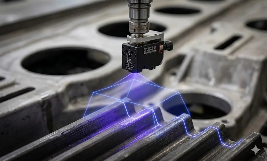
Emission: The laser view points down, serving as the projection of the line onto the target surface.
Detection (Camera Field of View): An angled lens acts as the camera viewing the projected line. The camera records the points with pixels, meaning the laser camera operates within a specific field of view.
Distance Calculation: An onboard digital signal processor analyzes the illuminated pixels from the camera to calculate the exact spatial distance of the surface.
Point Cloud Generation & Frequency: The camera records an image at a specific time frequency. For instance, a 60Hz frequency means the camera takes 60 frame grab pictures per second. If the camera has 2,000 pixels, it is able to capture 2,000 pixels multiplied by 60 frames per second, yielding 120,000 points per second.
When looking at visual representations of this process (such as a blue laser line projected onto a metal gear), it is important to note that the line touching the metal part represents exactly what the camera sees every frame grab. By rapidly capturing these pixel-based frames, the scanner creates a highly accurate 3D point cloud
Where Do Beginners Usually Get Confused?
Because "laser scanning" is an umbrella term across multiple industries, newcomers frequently mix up distinct technologies. Clearing up these common misconceptions helps establish the correct context for industrial applications:
Laser Scanners vs. Laser Cutters: A laser scanner uses low-power, eye-safe Class 1 or Class 2 lasers (often emitting just a few milliwatts). It purely collects geometric information and never melts, burns, or alters the physical workpiece. In contrast, laser cutters use high-wattage thermal lasers to cut or weld material.
Laser Scanners vs. 2D Cameras: Standard digital cameras capture flat, two-dimensional images made up of color pixels (R, G, B). They lack spatial depth information. A laser scanner measures depth and distance directly, recording three-dimensional spatial coordinates (X, Y, Z) regardless of the part's visual color.
Consumer vs. Industrial Metrology Systems: A retail barcode reader, an autonomous vehicle’s LiDAR sensor, and a high-precision manufacturing 3D scanner all operate on laser optics. However, while a vehicle LiDAR might operate with an accuracy tolerance of a few centimeters over hundreds of meters, industrial quality inspection systems deliver micron-level accuracy over small, intricate components.
How Laser Scanners Measure Distance: The Three Core Methods
To understand how laser scanners work across different operational environments, examine the three primary distance-measurement techniques. Each method relies on distinct optical physics, making specific scanner types suitable for different ranges, target sizes, and precision requirements.
Measurement Method
Underlying Principle
Operational Range
Primary Strengths & Limitations
Typical Applications
Time-of-Flight (ToF)
Measures the precise round-trip travel time of a pulsed laser beam bouncing off a surface using the known speed of light.
Long range (up to several kilometers).
Strengths: Extreme range capability. Limitations: Lower resolution for tiny, intricate part details.
Civil surveying, building architecture (AEC), terrain mapping, and autonomous vehicle navigation (LiDAR).
Phase-Shift
Emits a continuous, modulated laser wave and compares the phase difference between the outgoing wave and the returning reflected wave.
Medium range (1 to 100 meters).
Strengths: Faster data acquisition rates than ToF with higher precision. Limitations: Limited max distance compared to ToF.
Large industrial plant digitization, ship hull modeling, and pre-inspection of large aerospace components.
Optical Triangulation
Projects a laser line or dot onto an object, viewed by an internal camera offset at a fixed, known baseline angle. Trigonometric formulas calculate coordinates based on where the line strikes the camera sensor.
Short range (typically under 2 meters).
Strengths: Sub-millimeter and micron-level accuracy with extremely great detail. Limitations: Restricted working distance and line-of-sight constraints.
Precision manufacturing, reverse engineering, quality control inspection, and on-machine measurement.
Precision First: Resolution vs. Accuracy vs. Repeatability
When evaluating metrology specifications, confusing basic terminology is a common pitfall. A scanner with impressive headline numbers on a datasheet may not actually deliver the measurement integrity required for tight-tolerance manufacturing.
Understanding the distinctions between these key terms is critical:
Resolution: Describes the spatial density of the captured points, specifically, the smallest distance between two neighboring points in a 3D point cloud. Higher resolution captures finer surface details, sharp edges, and small radii, but it does not guarantee those points are spatially correct.
Accuracy: Quantifies how closely a measured dimension matches a certified reference standard or true physical value. For instance, if a reference gauge block is calibrated at exactly 50.000 mm and the scanner reads 50.002 mm, the measurement error is +0.002 mm (2 microns).
Repeatability (Precision): Indicates how consistently a scanner returns the exact same measurement when scanning the identical part multiple times under unchanged environmental conditions. High repeatability proves system stability and eliminates random measurement drift.
Volumetric Accuracy: Defines how measurement error grows as the measured volume increases. It is typically expressed as a base error value plus a length-dependent variable (for example, 20 μm + 15 μm / m). As the scanner moves further across a large structure, spatial error naturally accumulates.
Metrology buyers must evaluate accuracy and repeatability independently from raw point-density specifications to ensure the instrument meets engineering requirements.
Which Laser Scanner Type Matches Your Use Case?
Matching the scanner hardware to your operational scope prevents overspending on unnecessary range or purchasing an instrument lacking required accuracy:
1D & 2D Scanners: Basic single-point distance meters and single-line profilers used for automated package sizing, conveyor belt monitoring, or basic object presence detection.
Terrestrial & Surveying Scanners: Heavy-duty, tripod-mounted Time-of-Flight or Phase-Shift devices built for architectural captures, building information modeling (BIM), and site topography.
Handheld & Portable Arm 3D Scanners: Triangulation-based devices attached to articulated arms or guided by optical tracking targets, used by quality technicians in inspection labs.
Discovering how laser scanners work requires looking beyond optical hardware to examine data processing. A raw scan does not immediately yield an editable CAD file; it produces unstructured spatial data that must undergo specific software transformations.
The process follows a structured 4-step digital workflow:
The Physical Part (Data Capture): The process begins by measuring the physical workpiece using optical triangulation or laser line projection.
The Raw 3D Point Cloud (Registration): The scanner outputs raw spatial data. Specialized software filters out ambient noise and registers multiple scan angles together.
The Polygonal Mesh (Surface Extraction): The point cloud is converted into a triangulated surface mesh (STL/OBJ), creating a continuous digital skin over the part.
The Final Deliverable (CAD & GD&T): Finally, the software aligns the mesh features to generate a comprehensive GD&T inspection report, or exports the data as a parametric CAD model for reverse engineering.
How Does the Scanner Steer the Beam? (Mirrors, Galvanometers, and Lines)
To cover an entire three-dimensional surface, the scanner’s laser beam must move systematically across the target. Engineers use several mechanical and optical mechanisms to direct the light path:
Galvanometer & Rotating Mirrors: Motorized, high-speed mirrors oscillate along horizontal and vertical axes to deflect a single laser dot across a scene in a rapid raster pattern.
Polygon Prisms: High-speed spinning glass prisms sweep a laser beam continuously in one direction, ideal for high-throughput inline inspection environments.
Projected Laser Lines (Line Scanners): Instead of moving a single dot, modern industrial scanners pass the laser through a specialized cylindrical lens or diffractive optical element (DOE) to project an unbroken line of light across the part. An offset CMOS sensor records how this projected line bends over contours.
Using a solid laser line dramatically accelerates data capture rates while eliminating delicate moving mirrors inside the optical head. This design makes line scanners robust enough for vibration-prone environments, enabling seamlessintegration of blue-light laser sensors directly on machine tools.
From Point Cloud to Finished Model (Registration and Output)
Because a single scan view can rarely capture an entire object due to line-of-sight limitations, operators must capture multiple scans from different angles.
Specialized metrology software aligns these individual datasets into a unified coordinate space through a process called registration. The software identifies overlapping surface geometry or uses highly reflective reference target stickers to calculate the exact spatial transformation matrices required to merge the scans.
Once registered, the software filters out ambient lighting noise and converts the 3D point cloud into a triangulated polygon mesh (commonly an STL or OBJ file). From there, engineers can perform two distinct workflows:
Reverse Engineering: Converting mesh surface contours into clean, editable NURBS surfaces or solid CAD models (STEP, IGES).
Quality Inspection: Aligning the scanned data to an original nominal CAD model to generate color-coded deviation heatmaps and automated GD&T reporting.
Laser scanning technology has transformed quality control, structural documentation, and design workflows across diverse industries:
Aerospace & Defense: Verifying complex turbine blade airfoils, composite wing skins, and large structural fuselages where traditional contact gauges cannot measure flexible materials.
Automotive Manufacturing: Checking body-in-white (BIW) alignment, stamped sheet metal panels, and engine block castings for subtle surface sink marks.
Architecture, Engineering, & Construction (AEC): Digitizing historical structures for restoration, mapping complex piping networks inside chemical plants, and verifying as-built construction against structural drawings.
Tooling, Mold & Die: Inspecting deep core and cavity shapes in injection molds, forged dies, and press tooling to ensure parts meet tight dimensional standards before mass production.
Information Gain: What Laser Scanners Can and Can’t Capture
While non-contact optical scanning is extraordinarily fast, optical physics still governs it. Understanding its operational boundaries helps quality engineers select the correct inspection tools.
Captures Exceptionally Well
Optical Limitations & Physical Challenges
Complex Freeform Curves: Sweeping, organic contours like turbine blades, molds, and stamped panels.
Deep Bores & Narrow Slots: If the laser light cannot penetrate or the camera can't see the line (line-of-sight occlusion), it can't capture the data.
Flexible & Non-Rigid Parts: Thin sheet metal, rubber seals, and foam components that deform under tactile pressure.
Internal Threads & Features: Hidden internal chambers and small threaded holes are out of reach for line-of-sight optical beams.
High-Density Surface Datasets: Millions of surface points captured in seconds for full-field coverage.
Mirror-Like / Highly Reflective Surfaces: Specular reflection can scatter light away from the receiver, though modern blue-light systems mitigate this.
Dark Industrial Materials: Carbon fiber composites and dark rubber components, especially when using optimal laser wavelengths.
Transparent / Translucent Glass: Light penetrates the surface rather than reflecting off it, requiring temporary spray coatings.
Where optical line-of-sight is blocked by deep internal geometries, manufacturers combine laser scanning with tactile touch-trigger probing to achieve complete part coverage.
Why Laser Scanning Matters in Modern Manufacturing and How CAPPS-NC Extends It
Explaining how laser scanners work in an abstract lab setting is one thing, but applying that technology to a high-volume factory floor introduces practical challenges. Traditional metrology workflows require operators to unclamp a finished or semi-finished component from a machining center, clean it, transport it across the shop floor, and wait for a dedicated Coordinate Measuring Machine (CMM) in a climate-controlled room.
If the CMM reveals a dimensional defect, the part must be scrapped or reloaded onto the CNC machine, a process that introduces severe realignment errors and costly downtime.
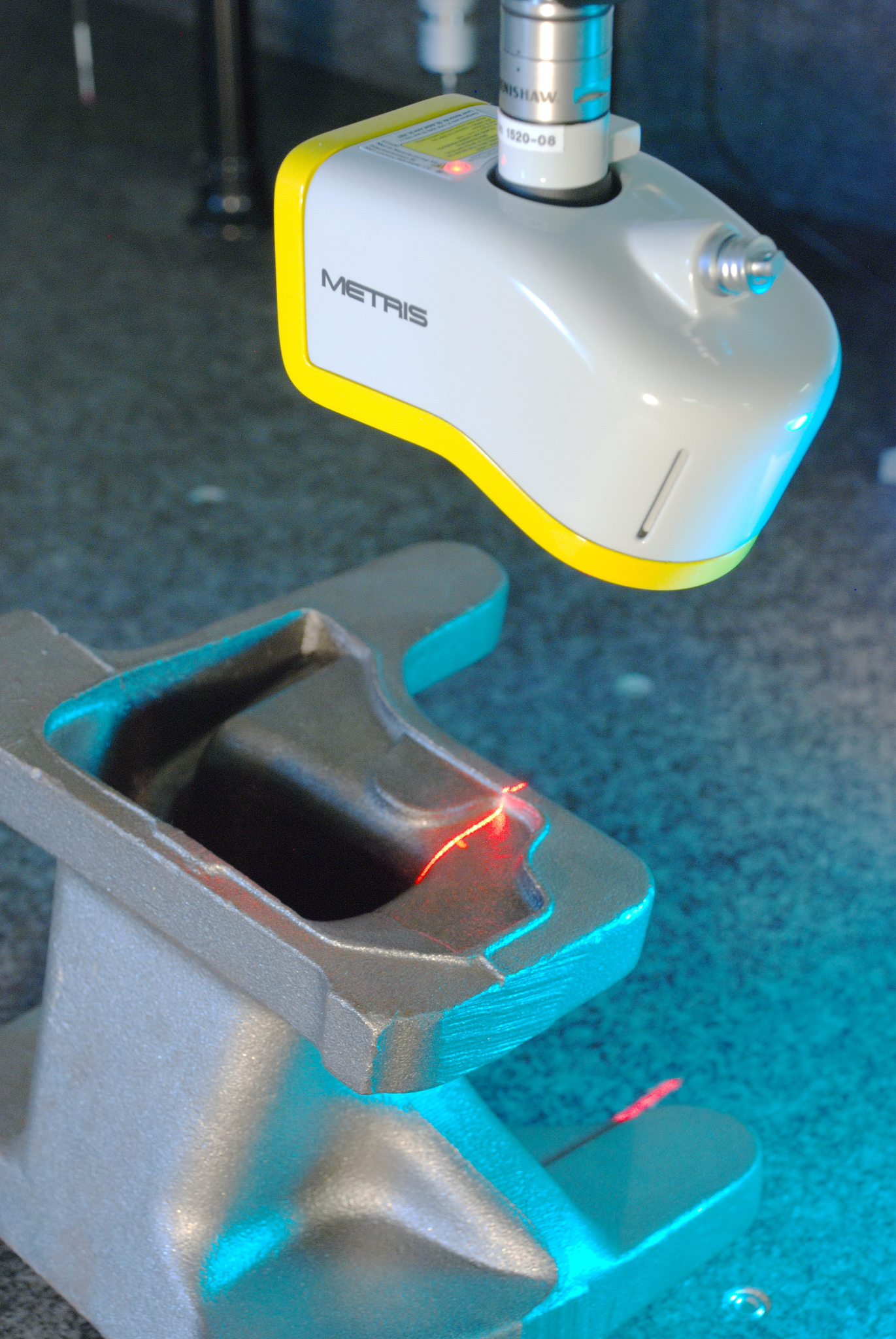
AAT3D’s CAPPS-NC software eliminates this bottleneck by bringing metrology directly into manufacturing. By mounting industrial blue-light laser sensors onto standard tool shanks, the laser scanner can be stored in the CNC machine’s automatic tool changer (ATC).
During an inspection step, the spindle picks up the laser scanner like a cutting tool, executes an automated scanning path across the part while it remains clamped on the machine bed, and transmits point-cloud data directly to CAPPS-NC.
This closed-loop setup unlocks significant operational benefits:
In-Cycle On-Machine Measurement: Surfaces are inspected instantly without disturbing the mechanical setup or losing reference zero coordinates.
Adaptive Manufacturing & Automatic Tool Offsets: CAPPS-NC analyzes incoming scan data in real time, automatically calculating and applying tool-wear compensation or work-offset adjustments back to the CNC controller before the final finishing pass.
Digital Twin Verification: Captures a high-density, verifiable digital record of the workpiece as it exists inside the machine tool, providing complete quality traceability.
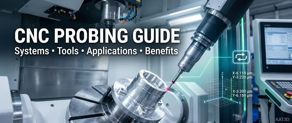
Dual-Sensor Synergy: Combines high-speed 3D laser surface scanning for complex contours with tactile touch-trigger probing for deep prismatic holes and internal threads within a single software environment.
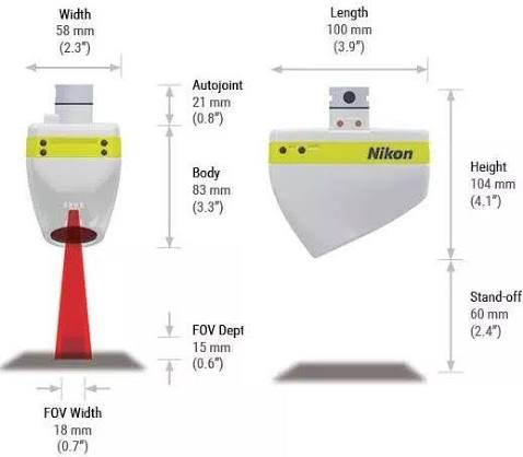
A prime example of this technology in action is AAT3D’s seamless integration with leading hardware manufacturers, such as the Nikon LC15Dx laser scanner. This system brings metrology-grade accuracy directly into 5-axis CNC machining centers, transforming production equipment into self-verifying manufacturing systems.
What the Market Emphasizes and Where AAT3D Adds Value
Current industrial trends emphasize closed-loop automation, total quality traceability, and reduced setup cycles. Standard standalone 3D scanners capture impressive visuals, but they leave a disconnect between measurement data and actionable machining corrections.
AAT3D bridges this gap by turning raw inspection data into direct machine control. By interfacing with major CNC controllers and industry-standard hardware from partners like Renishaw, CAPPS-NC instantly processes raw point clouds into full CMM-style GD&T reporting. This direct integration empowers manufacturers to catch deviations early, reduce scrap rates, and maintain micron-level tolerances across complex production runs.
Choosing a Laser Scanner: A Beginner’s Checklist
If your facility is evaluating laser scanning technology for quality control or production automation, use this objective checklist to guide your decision-making process:
Verify Accuracy vs. Headline Resolution: Do not evaluate a scanner based on point-density numbers alone. Demand certified accuracy and repeatability specifications tested against recognized standards (such as ISO 10360).
Assess Part Geometry & Line-of-Sight Limitations: Analyze your parts for deep internal cavities, narrow bores, or hidden undercut features. Determine if you require a hybrid system that pairs laser scanning with tactile touch-trigger probing.
Evaluate Surface Materials & Colors: If you routinely machine dark carbon composites, shiny polished aluminum, or translucent plastics, ensure the scanner utilizes advanced blue-light laser sensors designed to handle optical reflectivity variations without chemical sprays.
Determine the Operational Environment: Decide whether the scanner will operate exclusively in an isolated metrology lab or if productivity demands in-line, on-machine measurement directly on your CNC equipment.
Analyze Software Compatibility: Ensure the scanner’s software output connects directly to your existing CAD/CAM systems and can automatically generate comprehensive GD&T reporting.
If you need expert guidance on integrating advanced optical metrology into your machining workflows, contact the AAT3D technical team for a guided walkthrough.
How Do Laser Scanners Work (FAQs)
How Do Laser Scanners Work In Simple Terms?
A laser scanner projects a light beam, measures its reflection time or angular return, and calculates exact coordinates to generate a 3D point cloud.
What’s the Difference Between Time-Of-Flight, Phase-Shift, and Triangulation Scanning?
Time-of-flight measures light pulse travel time for long ranges; phase-shift analyzes wave displacement for medium ranges; optical triangulation uses offset cameras for high-precision, short-range part inspection.
Is a Laser Scanner the Same as a Laser Cutter?
No. A laser scanner projects low-power, eye-safe light purely to measure surface distances without burning, melting, or altering the workpiece material.
Can Laser Scanners Measure Shiny, Dark, or Transparent Surfaces?
Modern blue-light laser sensors measure dark and metallic surfaces effectively, though highly polished mirror surfaces or transparent glass may still require temporary anti-glare spray.
Does a Higher Point Count Mean a More Accurate Scan?
No. Point density (resolution) determines visual surface detail, whereas accuracy defines how closely those coordinates match true physical dimensions.
Can Laser Scanning Be Used Directly on a CNC Machine?
Yes. With CAPPS-NC, spindle-mounted laser sensors automatically scan parts on the machine bed, enabling real-time on-machine measurement and adaptive control.
Subscribe to our newsletter
Thank you! Your submission has been received!
Oops! Something went wrong while submitting the form.